Drayton Digistat 2 Wiring Diagram Wiring Diagram Pictures
Troubleshooting & Resources. If you've got a query on a technical issue, we have lots of information in our technical tips and FAQs. But if you can't find what you are looking for then send a tweet to @DraytonHeating, email customer.care@draytoncontrols.co.uk, or call our technical support team on 0333 6000 622. Wiring Diagrams.
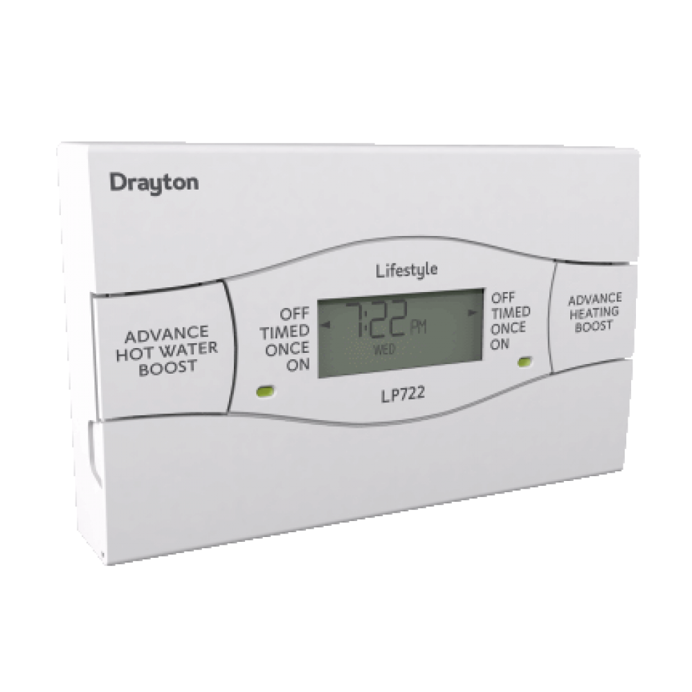
Drayton Lp722 Wiring Diagram Wiring Diagram
Title: Microsoft Word - Y Plan wiring diagram with RF receiver.doc Author: nickyj Created Date: 7/4/2012 4:38:31 PM
Drayton Lp822 Wiring Diagram

Turn the thermostat upto maximum e.g 30°C for now. If the wiser is heating only, put it where you stat was. Once you have it working and understand it, then think about moving wires. (you could put the red and yellow into the same terminal at the thermostat if you wanted) so it was bypassed. Here is a guide.
Drayton 3 Way Valve Wiring Diagram

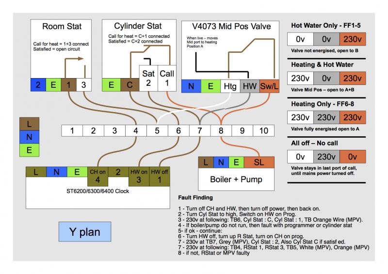
Y-Plan Wiring Diagram DHW & CH main switch 3A Fuse Extra Junction Box 230V from consumer unit 16A MCB + 30 mA RCD 2.5Mm or 6.0mm TE cable Power Switch 13A Fuse Neutral Switched Live Hot Water Off (G) C 1 2 (W) Pump. Title: Visio-wiring_2.vsd Author: admin Created Date:
Wiring Diagram Nest 3rd Generation

Part 4 in the heating wiring series covers how the 3 port mid position valve works internally, allowing 3 separate positions from only 2 mains inputs.Website.
Drayton Wiring Diagram

Documentation. Documentation. If you need to find any of our documents, they should be in this list below. Here you will find installation guides, brochures and user guides. If there is something you need that you can't find here, please call our Customer Services department on 0333 6000 622 or view our full catalogue.
[47+] Drayton 3 Port Valve Wiring Diagram, Drayton Central Heating Wiring Diagram IEKAATIKAGIRL

In-depth look at the Y plan system wiring and components and what they do. Ideal for heating engineers, electricians and apprentices or anyone that want to i.
YPlan 3 Port Valve cannot have CH on by itself? DIYnot Forums
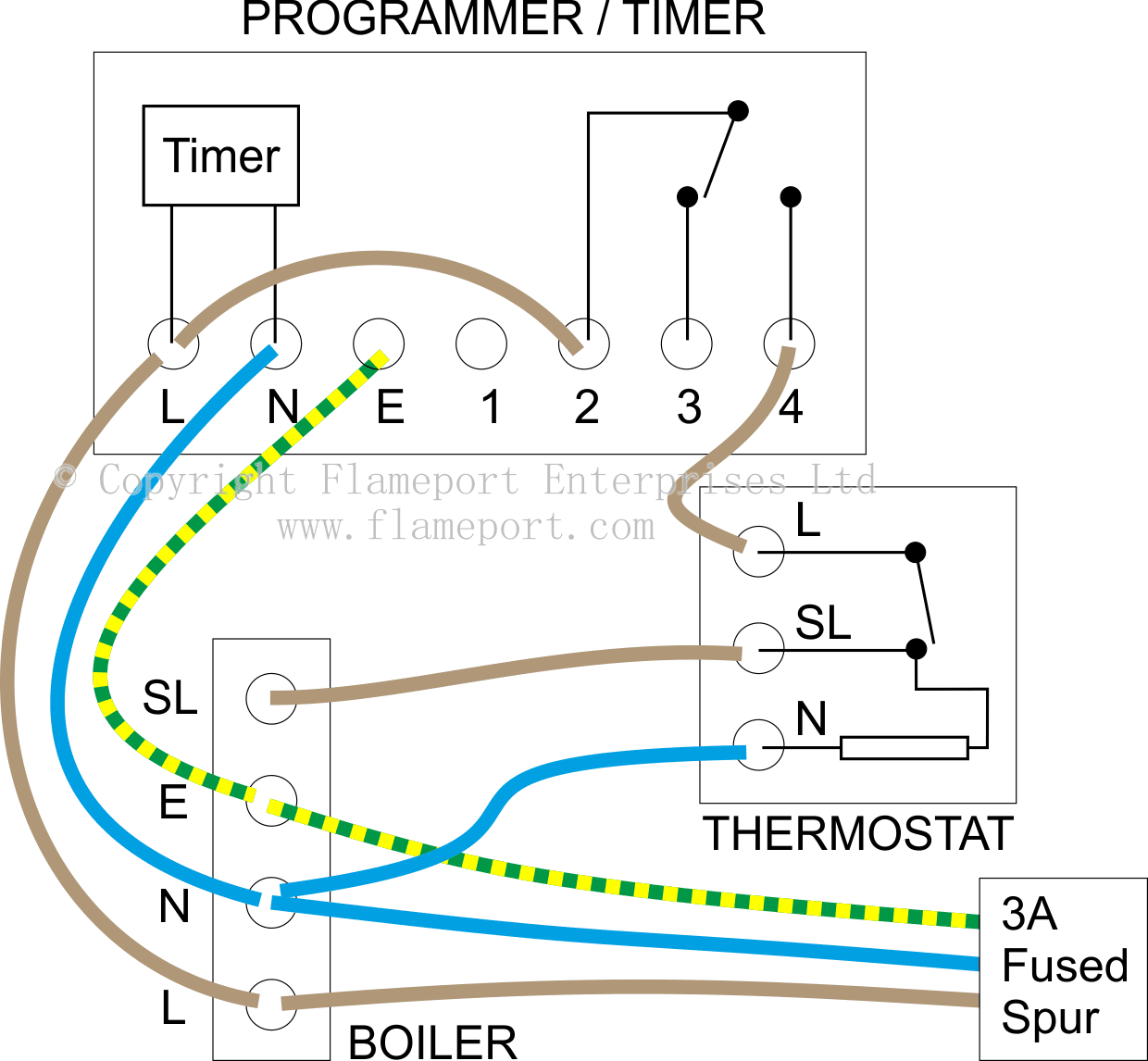
Y plan central heating & hot water programmer wiring diagram, shown below first is the cable (function) followed by the terminal number of the Y plan wiring centre. Live (L) = 1. Earth (⏚) = 2. Neutral (N) = 3. CH (on) = 4. HW (on) = 6. HW (off) = 7. Y Plan Programmer Schematic.
Drayton Lp112 Wiring Diagram Letterlazr
In this LearnElectrics video we will look at the wiring method of the Y Plan central heating system.This follows on from a previous video that looked at the.
S Plan Wiring Diagram With Frost Stat Wiring Diagram and Schematic

• Wiring diagrams • Smart controls. Contents. RTS Room Thermostat Range. For other variants see full Drayton catalogue. Product. Part No. SM1. 29205. SM2. RF601. Product. Part No. 22mm 2 Port zone valve - 5-wire SPST switch . 27100. 22mm Mid-position valve - 5-wire SPST switch. 27101.
Drayton Lp111 Wiring Diagram Letterlazd

Page 2: Installation Instructions. PLEASE NOTE: INSTALLATION MUST ONLY BE CARRIED OUT BY A QUALIFIED ELECTRICIAN OR HEATING ENGINEER. MAKE SURE MAINS INPUT HAS A 3 AMP FUSE. Lifestyle Timeswitch conforms to the essential requirements of these Directives: 2004/108/EC - Electromagnetic compatibility 2006/95/EC - Low voltage.
Drayton Ma1 Wiring Diagram Wiring Diagram

This video covers the 3 port valve. In particular its position in a Y plan system. We also cover the basics of installing or replacing a three port valve or.
Drayton Diverter Valve Wiring Diagram Wiring Diagram Pictures
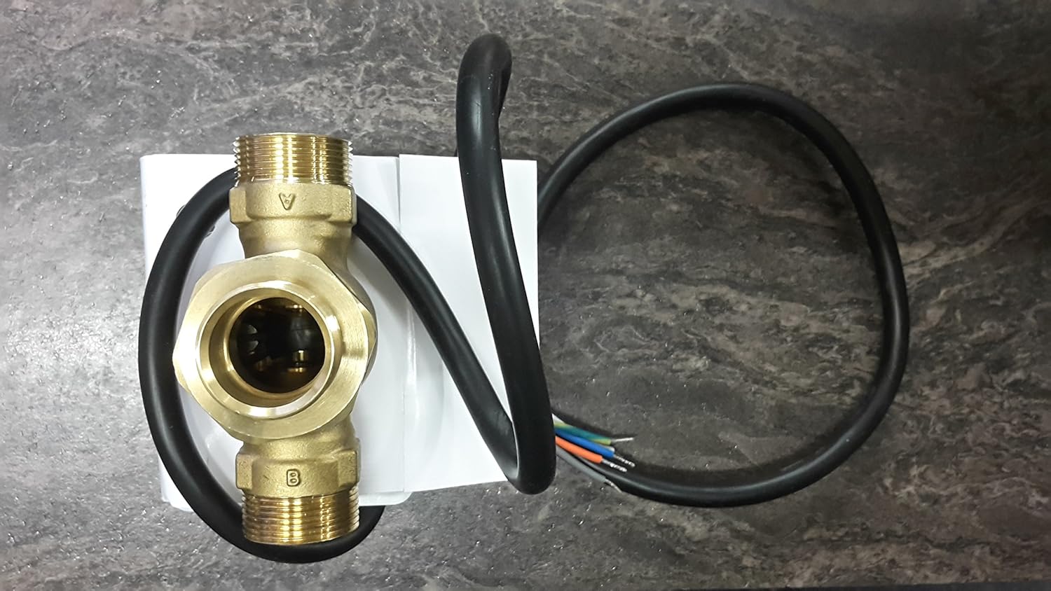
The flexible cable from the valve should be wired into a suitable wiring centre or junction box. The circuit must be protected by a fuse with a minimum rating of 3 amps. (Note: Cable is not field replaceable) Valves must be earthed. Wiring should be carried out by a competent Electrician and to current IET regulations. 982-307-426_F.
Drayton Lp241 Wiring Diagram Wiring Diagram Pictures
E D. 401 Southway Drive Plymouth PL6 6QT United Kingdom. Technical Helpline Tel: 0333 7000 622 customer.care@draytoncontrols.co.uk Website: www.draytoncontrols.co.uk. 090-669 Iss B.
Drayton Tempus Three Wiring Diagram

Operation - Hot water only. Power starts at terminal 3 (HW On) in the programmer. This passes via the wiring centre terminal 6 to the cylinder thermostat. If heat is required, power continues to terminal 8 in the wiring centre, and on to the boiler and pump. The valve is not powered at all, and the spring holds it in position B, so water from.
Drayton Lp522 Wiring Diagram Wiring Diagram
There are five terminals wired in it. 1 = live in, 2 = neutral. 3 is not used. 4 = boiler live and 5 = boiler neutral. The wire to the actuators is doubled up with the live in to terminal 1. Which means there's always power going to the actuators and thermostat. macme, Aug 3, 2019. #3.
.